The actual shape of blower performance curves is determined by the combined effect of the hydraulic losses of the impeller and casing. Mechanical losses including disk friction remains the same for all capacities and leakage loss is small and varies slightly with the impeller head near the shaft. Usually for the design, comparison and critical assessment of blower the dimensionless coefficients are adopted. This is done so as to arrive at the performance values which are independent of actual increase in pressure, flow rate, physical and other properties. The user on the other hand is concerned with the head increase in the blower and the volume flow rate, so investigation of flow in casing helps in minimizing loses and selection of appropriate casing for the impeller. The performance coefficients of blower are pressure coefficient ψ, flow coefficient φ, diameter coefficient δ and speed coefficient σ. Pressure coefficient or the pressure rise coefficient is defined as the ratio of the difference between the static pressure at the exit flange of the blower and the total pressure at the inlet flange of the blower to the dynamic head corresponding to the peripheral speed at the exit of the rotor of the blower. Therefore it important to investigate the flow inside the casing where there is transformation of energy to pressure rise.
Ψ = ∆p / (1/2*ρU2 2 )
Flow coefficient or volume coefficient is defined as the ratio of the volume flowing through the blower to the theoretical volume calculated on the basis of peripheral speed at the exit of the rotor of the blower and the passage area at the exit of the rotor of the blower. In other words it the ratio of the radial or the meridional velocity at the exit of the rotor to the peripheral speed at the exit of the rotor of the blower. As peripheral speed is depending upon the diameter, speed and width of impeller, so width of casing can be deciding parameter for design of casing.
Φ = Vr2 / U2
This is obtained from
Φ = Q / π *D2 *b2 *U2
The speed coefficient σ is also known as shape factor as it gives the overall shape of the machine based on its duty, i.e. the pressure head and flow rate. It is also called specific speed and written as Ns . The speed coefficient or the specific speed is given as
Ns = Φ0.5 / ψ 0.75
The diameter coefficient δ is given by
δ = ψ0.25 / Φ0.5
The relation between the flow parameters is
ψ = (Φδ2 )
The performance of a blower is usually presented in term of variation of pressure coefficient with flow coefficient.
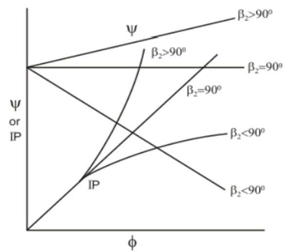
The characteristics in figure: 1.1 depict the following
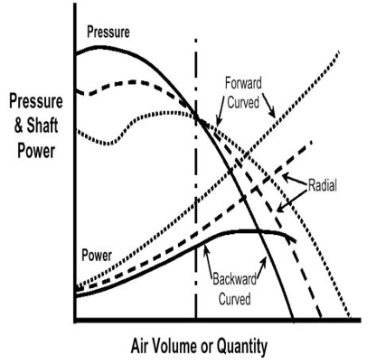
(i) Forward curved fans β2>90° develop the highest pressure for a given impeller diameter and speed.
(ii) Power requirement of a forward curved fan increases steeply for a small change in flow rate.
(iii) Pressure developed decreases fast with increasing flow rate in a backward curved fan.
In conclusion, the forward curved fans have large volume discharge and pressure rise but they demand higher power. However, forward curved fans are unstable for off-design operating conditions.
Backward curved fans are very efficient and the drooping power characteristic makes them suitable for a better off-design performance. Radial curved fans are preferred for dust-laden fluids. Due to their shape, the solid particles are not stuck and deposited on the blade surface. Specific speed is basic for selection of design of casing. Size of casing with rise in pressure differs with the outlet blade angle. So flow behavior changes drastically in the casing from backward to forward impeller. So one should have an idea regarding fitting of impeller in casing, which might be design for different blade angle. What should be the range for selecting the blade for designing the casing? The effect of disturbance of flow in casing will be mainly at off-design condition.
ACTUAL CHARACTERISTICS OF A CENTRIFUGAL IMPELLER
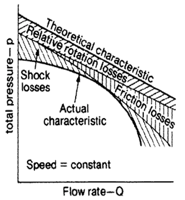
The actual characteristics of the centrifugal impeller are obtained by deducting the stage losses from the theoretical head or pressure coefficient. Therefore the nature of the actual characteristic depends on the manner in which the stage losses vary with the operating parameters. Friction and shock losses affect the performance significantly. In all cases, friction and shock losses produce pressure-volume curves that tend toward zero pressure when the machine runs on open circuit, that is, with no external resistance. Figure: 1.3 shows a typical pressure-volume characteristic curve for a backward blade.
Frictional losses occur due to the viscous drag of the fluid on the faces of the vanes. A diffuser effect occurs in the diverging area available for flow as the fluid moves through the impeller. This results in a further loss of available energy. In order to transmit mechanical work, the pressure on the front face of a vane is necessarily greater than that onthe back side. A result of this is that the fluid velocity close to the trailing face is higher than that near the front face. These effects result in an asymmetric distribution of fluid velocity between two successive vanes at any given radius and produce an eddy loss. The transmission of power is not uniform along the length of the blade.
The separation losses occur particularly at inlet and reflect the sudden turn of near 90° as the fluid enters the eye of the impeller. In practice, wall effects impart a vortex to the fluid as it approaches the inlet. By a suitable choice of inlet blade angle β1, the shock losses will not be in lower range of blower and may be small at the optimum design flow. An inlet cone at the eye of the impeller or fixed inlet and outlet guide vanes can be fitted to reduce shock losses. In the development of the theoretical pressure and power characteristics, we assumed radial inlet conditions. When the fluid has some degree of pre-rotation, the flow is no longer radial at the inlet to the impeller. The second term in Euler’s equation takes a finite value and again, results in a reduced blower pressure at any given speed of rotation.
The combined effect of these losses on the three types of centrifugal impeller is to produce the characteristic curves shown on figure: 1.2. The non-overloading power characteristic, together with the steepness of the pressure curve at the higher flows, are major factors in preferring the backward impeller for large installations as shown in figure: 1.3. All the above losses will be there in the blower but losses in casing due outlet blade angle, shape of the casing and angle of the tongue plays major role in the actual performance of the blower. For determining the major losses inside the casing can be achieved by the detail analysis of flow at various positions inside the casing.
EFFICIENCY OF BLOWER:
The blower efficiency is defined as a ratio of the energy output to the energy input. The true efficiency of air blower is a definite physical quantity depending upon the degree of perfection of hydraulic and mechanical design as shown in figure: 1.4. In actual practice, it is very difficult to determine a true head from inlet and outlet pressures and energy input.
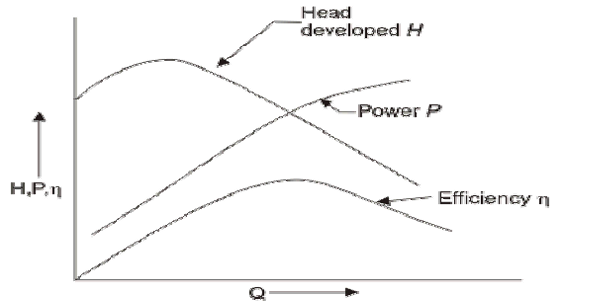
Figure: 1.4 Performance characteristic curves of a centrifugal blower.
The ’total’ or ‘gross’ blower efficiency is consisting of several partial efficiencies. They are:
Mechanical efficiency ηm = Brake horse power – Mechanical losses/Brake horse power
Where, mechanical losses include bearing, mechanical seal and impeller disk friction losses.
Volumetric efficiency ηv= Q/Q+QL
Where, Q is the measured volume of flow and QL is the leakage through the sealing rings which is bypassed back to the impeller inlet.
Hydraulic efficiency ηh=H/H+hL
Where H is the head in feet available at blower discharge and hL represents hydraulic losses through blower passages, including skin friction and eddy losses.
It can be noted that all the above three partial efficiencies account for losses of volume (or weight of flow), head and power.
These partial efficiencies are connected to the total efficiency as follows:
ηT= ηh*ηv*ηm
In determining the total efficiency of blower, Mechanical efficiency will be fixed and limited as per the bearing and seals provided. Major role is of Volumetric and Hydraulic efficiency, which depends upon the casing flow. In investigating the flow inside the casing helps in determining the eddy losses and passage losses of the Blower.
Related Posts:
Air blowers generally use centrifugal force to propel air forward. Inside a centrifugal air blower is a wheel with small blades on the circumference and a casing to direct the flow of air into the center of the wheel and out toward the edge…
Introduction of Different Sections of Blower
Blower is power consuming machine, where large volumes of gas or air at low pressure are required. According to the “Compressed Air Institute”, it is a machine to compress air or gas by centrifugal force to a final pressure not exceeding…