Fans are typically driven by alternating current (AC) motors. In industrial fan applications, the most common motor type is the squirrel-cage induction motor. This motor type is commonly used because of its characteristic durability, low cost, reliability, and low maintenance. These motors usually have 2 or 4 poles, which, on a 60- hertz system, translate to nominal operating speeds of 3,600 revolutions per minute (rpm) and 1,800 rpm, respectively. Although motors with 6 poles or more are used in some fan systems, they are relatively expensive. The most common class of motors for fan applications is NEMA Design B. Service factors range from 1.1 to 1.15, meaning that the motors can safely operate at loads between 110 to 115 percent of their horsepower (hp) ratings.
The installed motor should be checked for sufficient starting torque to overcome the inertia of the fan wheel and drive package, and accelerate the fan to its design speed. A characteristic of induction motors is that their torque is directly related to slip, or the difference between the speed of the magnetic field and the speed of the motor shaft. Consequently, in many fans, actual operating speeds are usually around 2 percent less than their nominal speeds. For example, a theoretical four-pole induction motor with no slip would rotate at 1,800 rpm with a 60-hertz power supply; however, rated operating speeds for this motor are usually around 1,750 rpm, indicating that slip rates are a little over 2.7 percent at rated load. Fans that are driven by older motors are probably operating at much lower efficiencies and at higher levels of slip than what is available from new motors. Remember the fan laws; the fan operating at low RPM will provide low airflow. EPAct efficiency motors operate with less slip, which means fans rotate at slightly higher speeds.
Fan Motor Controller
All fans are suitable for direct on line starting manually or automatically up to and including 5.5kW. The number of starts should be limited to no more than four direct-on-line starts per hour or, no more than eight starts per hour for motor up to 1kW. The controller is the switch mechanism that receives a signal from a low power circuit, such as an on/off switch, and energizes or de-energizes the motor by connecting or disconnecting the motor windings to the power line voltage. In conventional systems, the high in-rush and starting currents associated with most AC motors creates power quality problems, such as voltage sag. Soft starters gradually ramp up the voltage applied to the motor, reducing the magnitude of the start-up current. As industrial facilities increase the use of computer-based equipment and control systems, soft starters are becoming important parts of many motor control systems. In fact, a major advantage associated with most VFDs is that they often have built-in, soft-start capabilities. The VFD provides multiple speed capability and provides energy savings in cube root of RPM.
Fan Drive System
Motors are connected to fans either directly, through a gearbox, or, more commonly, by a belt system. There are advantages and drawbacks to each drive option. Understanding how drives are selected can be helpful in correcting problems that are the result of poor design.
Direct Drives
In direct drive systems, the centrifugal fan is attached to the motor shaft. This is a simple, efficient system but has less flexibility with respect to speed adjustments. Because most fans are operated with induction motors, the operating rotational speeds of direct drive fans are limited to within a few percent of the synchronous motor speeds (most commonly 1,200, 1,800, and 3,600 rpm). The sensitivity of fan output to its operating rotational speed means that errors in estimating the performance requirements can make a direct-drive system operate inefficiently (unlike belt drives, which allow fan rotational speed adjustments by altering pulley diameters). In axial fans, direct drives have some important advantages. Applications with low temperatures and clean system air are well suited for direct drives because the motor mounts directly behind the fan and can be cooled by the airstream. This space-saving configuration allows the motor to operate at higherthan-rated loads because of added cooling. However, accessibility to the motor is somewhat restricted. Direct drives have several advantages over belt drives, including higher efficiency, compact space requirements, and lower maintenance. Although belt drives are occasionally used in fan applications over 300 hp, they are rarely found in fan applications over 500 hp. At these power levels, the efficiency advantages of direct drives are very attractive.
One way to add rotational speed flexibility to a direct-drive system is to use an adjustable speed drive (ASD). ASDs allow a range of shaft speeds and are quite practical for systems that have varying demand. ASDs can provide a highly efficient system for fans that operate over a range of conditions.
Belt Drives
Because the required rotational speed of a fan is usually less than motor rpm, belts are used to transfer power from a motor pulley (sheave) to a fan pulley with a larger diameter. The desired fan rotational speed can be achieved using various pulley sizes according to the following relationship:
Drive Ratio=Motor RPM/Desired Fan RPM
Or
RPMdriven=RPMdriver×D driver/D driven
Where D is the diameter of the pulleys
Most industrial fan belt drive applications are limited to speed ratios below 4:1 (the motor speed is 4 times faster that the fan speed); however, for small horsepower applications (less than 1 hp), this ratio can be as high as 10:1. The limiting factors on speed ratios are the practical size of the pulleys, the arc of contact between the belt and the drive pulley, and belt speed.
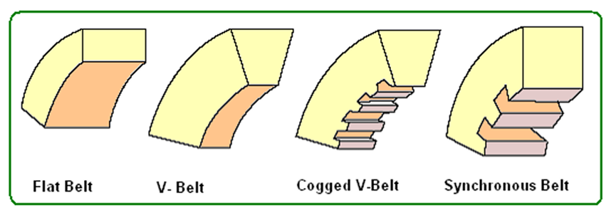
Belt drives offer a key advantage to fan systems by providing flexibility in fan speed selection. If the initial estimates are incorrect or if the system requirements change, belt drives allow flexibility in changing fan speed. In axial fans, belt drives keep the motor out of the airstream, which can be an advantage in high temperature applications, or in dirty or corrosive environments. The four principal types of belts are flat, V-belts, cogged V-belts, and synchronous.
- Flat belts have a uniform cross-section and transmit power through friction contact with flat pulley surfaces.
- V-belts are an improvement over the flat belt, using a wedging action to supplement friction-based power transfer. V-belts have a long history in air blower, which means there is a lot of industry knowledge about them. An important advantage to V-belts is their protection of the drive rain during sudden load changes. Service conditions that experience sudden drive train accelerations causes accelerated wear or sudden failure.
- Cogged V-belts offer the same advantages as V-belts; however, their notched design provides additional flexibility that allows the use of smaller pulleys. Cogged V-belts are slightly more efficient than conventional V-belts, because of their added flexibility and the fact that the notched surface transfers force more effectively. In applications where a small arc of contact is unavoidable, the use of cogged V-belts is recommended.
- Synchronous belts offer many advantages over standard flat belts and V-belts. By using a mesh engagement, synchronous belts are the most efficient type of belt drive because they do not suffer efficiency losses through slip. Synchronous belts have teeth that engage with grooves in the sheave. Synchronous belts can allow lower belt tension than conventional belts, reducing the radial loads on motor and fan bearings and extending their operating lives. Further, synchronous belts do not lose efficiency as they wear. However, synchronous belts are very noisy, which often discourages their use. They also transfer shock loads through the drive train without allowing slip. These sudden load changes can be problematic for both motors and fans. Another problem with synchronous belts is the limited availability of pulley sizes. Because the pulleys have a mesh pattern, machining them alters the pitch diameter, which interferes with engagement. Consequently, pulleys are available in discrete sizes, which preclude an important advantage of belt drives: the ability to alter operating rotational speeds by adjusting sheave diameters. Because of these factors, synchronous belts are not as widely used as Vbelts in fan applications.
The required belt capacity must not only include the horsepower required by the driven load; it must also account for site-specific factors, such as temperature, service factor, and arc of contact. The effect of temperature varies according to the belt material. Rubber contracts at higher temperatures. Consequently, in belts that have high rubber content, tension and stress increase as the drive system temperature increases. Because temperature also affects the mechanical strength of a belt, belts should be sized to meet the torque requirements at the highest normal operating temperature. The belt service factor accounts for acceleration loads during start-up and under load changes. For most fans, the belt service factor is between 1.2 and 1.4.
In general, synchronous belts are the most efficient, while V-belts are the most commonly used.
Gear Drives
Gear drives are not as common as belt or direct drives, but are useful in a few applications that require special configurations between the fan and motor. Gear systems have a wide range of efficiencies that depend on gear design and speed ratio. Gear systems can be very robust, affording high reliability—a characteristic that is very important in fan applications with restricted access to the drive system. However, gears, unlike belt systems, do not allow much flexibility in changing fan speed. Gear-system efficiency depends largely on speed ratio. In general, gear efficiencies range from 70 to 98 percent. In large horsepower (hp) applications (greater than 100 hp), gear systems tend to be designed for greater efficiency because of the costs, heat, and noise problems that result from efficiency losses. Because gears require lubrication, gearbox lubricant must be periodically inspected and changed. Also, because gears—like synchronous belts—do not allow slip, shock loads are transferred directly across the drive train.
Bearing Life
Bearing life is determined in accordance with methods prescribed in ISO 281/1-1989 or the Anti Friction Bearing Manufacturers Association (AFBMA) Standards 9 and 11, modified to follow the ISO standard. The life of a rolling element bearing is defined as the number of operating hours at a given load and speed the bearing is capable of enduring before the first signs of failure start to occur. Since seemingly identical bearings under identical operating conditions will fail at different times, life is specified in both hours and the statistical probability that a certain percentage of bearings can be expected to fail within that time period. For Example, a manufacturer specifies that the bearings supplied in a particular fan have a minimum life of L-10 in excess of 40,000 hours at maximum cataloged operating speed. We can interpret this specification to mean that a minimum of 90% of the bearings in this application can be expected to have a life of at least 40,000 hours or longer. To say it another way, we should expect less than 10% of the bearings in this application to fail within 40,000 hours. L-50 is the term given to Average Life and is simply equal to 5 times the Minimum Life. For example, the bearing specified above has a life of L-50 in excess of 200,000 hours. At least 50% of the bearings in this application would be expected to have a life of 200,000 hours or longer.
Some common conditions to consider in designing a satisfactory drive are:
- Drives should be installed with provisions for center distance adjustment.
- This provision is important because all belts stretch.
- Centers should not exceed 2-½ to 3 times the sum of the sheave diameters or be less than the diameter of the larger sheave.
- The arc of contact on the smaller sheave should not be less than 120 degrees.
- Sheave diameter ratios should not exceed 8:1.
- Belt speed preferably should not exceed 5,000 ft/min, or be less than 1,000 ft/min—4,000 ft/min is the best practice.
- Sheaves should be dynamically balanced for speeds in excess of 5,000 ft/min rim speed.
Some helpful points to watch for when installing drives are as follows:
- Be sure that shafts are parallel and sheaves are in proper alignment. Check again after a few hours of operation.
- Do not drive sheaves on or off shafts. Wipe shaft, key, and bore clean with oil. Tighten screws carefully. Recheck and retighten after a few hours of operation.
- Belts should never be forced over sheaves.
- In mounting belts, be sure the slack in each belt is on the same side of the drive. This side should be the slack side of the drive.
- Belt tension should be reasonable. When in operation, the tight side of the belts should be in a straight line from sheave to sheave, and with a slight bow on the slack side. All drives should be inspected periodically to be sure belts are under proper tension and are not slipping.
- When making replacements of multiple belts on a drive, be sure to replace the entire set with a new set of matched belts.
Related Posts:
Fan drives can be reduced to two basic types: indirect drives (belt drives) and direct drives. Both types have strengths and weaknesses that should be considered carefully during selection…
Belt Drive Maintenance Guidelines
Belt tension and alignment should be checked periodically. Proper belt tension is typically the lowest that prevents a belt from slipping at peak load. An important maintenance practice to avoid is the use of…