A typical supply fan or impeller (wheel) can be described by the blade constructions. The distinguishing characteristic is the shape of the individual fan blades and their orientation relative to wheel rotation. The airfoil (AF) fan has contour blades that curve away from the direction of rotation. The backward incline (BI) fan is slightly less efficient but similar to the AF fan; the BI wheel has single thickness blades that also curve away from the direction of rotation. The forward-curved (FC) fan blades curve into the direction of wheel rotation.
This paper will focus on the application of FC and AF fans. See Table A in the Appendix for a comparison summary of these types of fans.
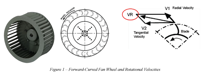
Forward-Curved (FC) Fans
Forward-curved fan blades curve into the direction of wheel rotation, producing an air velocity at the blade tip (VR) which is actually greater than the tip (tangential) velocity itself (V2). See Figure 1. This effectively means that a forward-curved fan can move air at greater velocities while requiring less rotational speed than other centrifugal fan types.
Forward-curved fans are the most commonly used wheel type in HVAC equipment. Forward-curved fans are typically used in low-pressure applications (under 5.0 in. wg), since they can satisfy airflow requirements at lower rotational speeds (typically 800 to 1200 rpm). As a result of lower operating pressures, the design of the forward-curved fan is usually lightweight when compared to other fans and typically has the lowest cost among fan types.
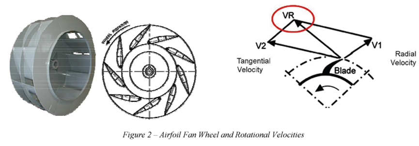
Airfoil (AF) Fans
Airfoil fans are comprised of individual airfoil blades. Each blade is oriented with the tip pointing opposite to the direction of rotation. This backward orientation results in an air velocity (VR) that is slower than the blade-tip velocity (V2). (See Figure 2.) The result is that the airfoil fan must rotate with higher tip speed than a FC fan in order to move the same amount of air.These higher rotational speeds (1200 to 3000 rpm) and additional stress during operation require a sturdier, more substantial blade cross section and fan structure than that of a slower, forward-curved fan.
Airfoil fans are typically applied in high static applications, ranging from 5 to 10 in. wg or higher.The AF fans are fundamentally more efficient than FC fans due to the ability of the AF fan to produce more of the static pressure rise within the wheel itself. The FC wheel produces little static pressure in the wheel and relies on the scroll of the fan housing to change velocity into static pressure.
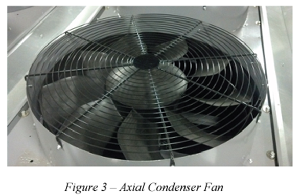
Axial Fans
Sometimes referred to as propeller fans, these fans move a great quantity of air, but have very little static pressure capability. In HVAC products, they are almost always used for condenser fans. They may be used for light static exhaust fans.
Figure 3 shows an example of a high-efficiency low noise shrouded outdoor (condenser) fan.
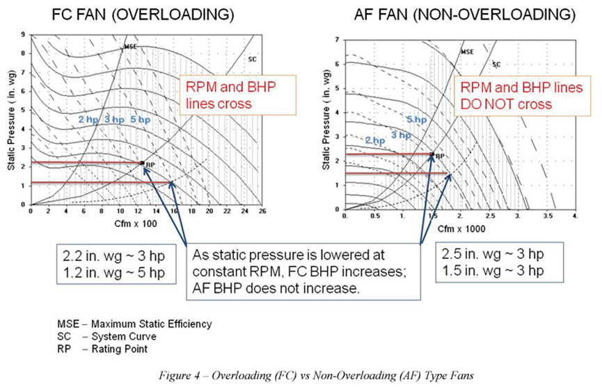
Overloading vs Non-Overloading Fans
Another significant difference between FC and AF fans is that, unlike the FC fan, the AF is considered to be a “non-overloading” fan, as it requires relatively constant power input at a given speed, regardless of airflow conditions. As static pressure is lowered at a constant rpm, the fan’s bhp remains relatively constant and thus does not “overload.”
Forward-curved fans have an overloading horsepower characteristic. In an overloading type fan, as the fan remains at constant rpm and the static pressure is decreased, the brake horsepower requirements of the fan will increase thus “overloading” the fan and motor.
Figure 4 shows the difference between an overloading type fan (FC) and a non-overloading type fan (AF). The FC fan increase in bhp at constant rpm can easily be seen. As the static pressure decreases (shown by the red lines in the graphs below) the rprm lines cross the bhp lines at the points shown by the blue arrows. This increase in bhp may result in over working and damaging the motor. The AF fan has rpm lines and bhp lines that are nearly parallel to one another. Airfoil fans, which have the highest rpm capabilities of all fan choices, may require the highest motor horsepower for those high rpm operating points.
In new construction where ductwork is not complete or when ducting is changed for remodeling, caution should be taken to make sure that the centrifugal fan does not operate in the overloading area. Overall static pressure on the fan must be maintained.
Related Posts:
Principle of Operation Centrifugal – Operating principle is a combination of deflection by the blades as well as the centrifugal force exerted on the air rotating with the wheel and thereby moving outward in a radial direction…
Centrifugal Fan Performance Curves
As you have known, you must know what the capacity of a fan is before you consider opening a damper or increasing the fan speed. Doing so may not be safe—it could result in an overloaded motor, for example…