Imagine a fan selected with great care to provide exactly the performance required in the specifications. Once installed, the air balancer reports that air performance is considerably lower than required. What went wrong?
The answer is probably system effect.
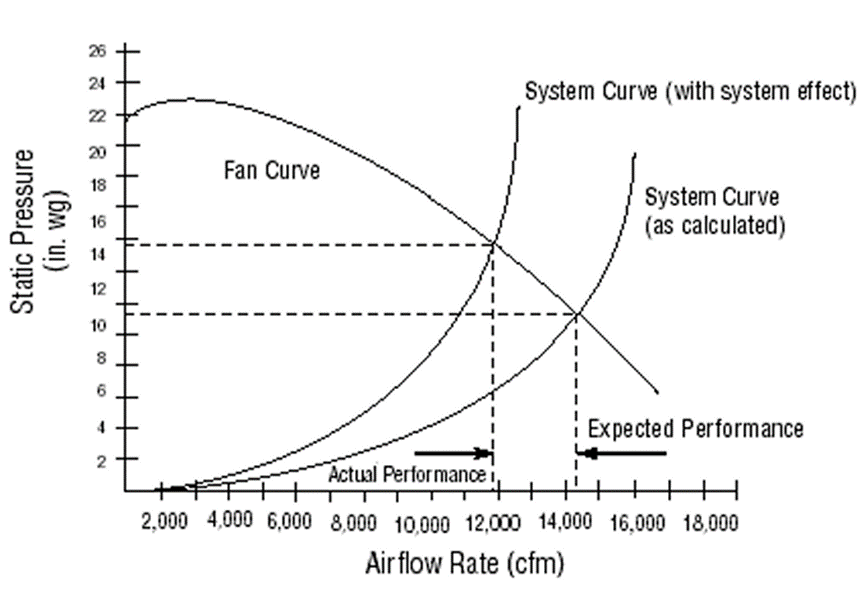
The system effect is the change in system performance that results from the interaction of system components. The Air Movement and Control Association (AMCA) define system effect as “a pressure loss, which recognizes the effect of fan inlet restrictions, fan outlet restrictions, or other conditions influencing fan performance when installed in the system.” Typically, during the design process, the system curve is calculated by adding the losses of each system component (dampers, ducts, baffles, filters, tees, wyes, elbows, grills, louvers, etc). The loss of pressure due to all of these sources, known as the system resistance, is for practical purposes proportional to the square of the velocity at the point of loss. As velocity varies directly as volume, we can say that resistance varies as the square of the volume or for a fixed system, it may be said that the pressure required to pass a given volume of air through the system will vary as the (volume flow rate) ², therefore, if it is required to double the air flow through a system, the centrifugal fan must be capable of providing twice the volume flow rate at four times the original pressure! AND EIGHT TIMES THE FAN MOTOR POWER!
The governing equation for pressure loss across any particular component is:
∆p=C(V/1097)2ρ
Where:
Δp = pressure loss in inches of water gage (in-wg)
C = loss coefficient for the component
V = velocity in feet per minute
ρ = density of the airstream (0.075 pounds per cubic foot at standard conditions) The loss coefficient, C, is a dimensionless indicator of flow resistance.
The loss coefficient is based on uniform flow into and out of the system components such as ducts, fittings, and components, the values of which are typically listed in tables provided by manufacturers. During the system design phase, designers calculate system resistance curves based on the published loss coefficients for each component. However, system configurations that promote non-uniform flow conditions will create flow resistances that are higher than anticipated, leading to under-performing systems. The result of this equation is illustrated in system curve below.
What are the penalties of system effect?
The penalty starts with fans selected at higher speeds to compensate for additional losses. Higher speeds result in larger motors, increased cost, reduced efficiencies, increased vibration, and acoustical effects. The severity depends on how inadequate the fan to system connection is. For example, if 20% more air is required, the fan speed will need to be increased 20%. The resulting static pressure will be 44% higher and the BHP will be 73% higher than the original values. New fan drives and a larger motor may be required.
Direct drive fans present a greater problem than belt drive fans. In some cases, it’s not possible to use the existing fan unless the installation can be modified to eliminate or reduce the causes of system effect.
How to minimize system effects?
To solve deficient fan system performance problems, it helps to have a clear understanding of fan and system curves plus knowledge of how to apply the fan laws. To minimize system effects, air must enter or leave a fan uniformly. However, in many cases space constraints or other factors prohibit designers to allow for ideal conditions. The following conditions cover the most common causes of system effect.
Inlet Conditions
- Elbows too close to fan inlet
- Abrupt duct transition
- Inlet spin due to duct design
- Dampers not fully open
- Damper locations
- Poorly designed guards
- Inlet too close to walls or bulkhead
- Inlet boxes
Outlet Conditions
- Elbows too close to fan outlet
- Abrupt transitions
- Free discharge
- Damper location
- Weather hoods
- Discharge guards
- Discharge too close to wall or bulkhead
The system effect can be particularly problematic when the airflow into or out of a fan is disrupted into a highly non-uniform pattern. Poor configuration of ductwork leading to or from a fan can severely interfere with a fan’s ability to efficiently impart energy to an airstream. For example, placing an elbow close to the fan outlet can create a system effect that decreases the delivered flow by up to 30 percent. This can require an increase in fan speed, which in turn results in an increase in power and a decrease in system efficiency. The figures below illustrate the concept.
Related Posts:
The Different Type of Fans’ System Effect Test
Roof Exhaust Fans Figures below illustrate how roof exhausters are tested; AMCA refers to Fig#1 setup as “Type A: Free inlet, free outlet”.Fig # 2 & 3 illustrate roof exhaust fan installations having system effects…
Fan Performance Evaluation and Efficient System Operation System Characteristics
The term “system resistance” is used when referring to the static pressure. The system resistance is the sum of static pressure losses in the system…